Saturday, August 27, 2011

Bent Lamination Bench Continued

At the end of this summer I finally got a week to continue working on my furniture project which I started in the furniture design/build class I took last summer. The project is a small bench I designed to explore bent lamination techniques; I posted most of what I accomplished last summer here http://blog.josephpeltier.com/2011/03/summer-10-furniture-design.html and here http://blog.josephpeltier.com/2011/03/summer-10-furniture-building.html.

I have since tweaked the geometries slightly based on what I learned while fabricating the bench last summer, here are recent drawings of the bench.


The last formworks I made were out of MDF and after a year a lot of them took on water and I had to toss them out. I took the opportunity to put more thought into designing the formwork so that they will be sturdier and easier to clamp the bent plys, I am planning on making them out of 3/4" plywood.

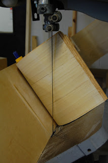
The most complicated part of the design is where the X-bracing on the sides hits the floor. When I fabricated this part before I made the lamination wider and then bandsawed the bent form at an angle to achieve what appeared to be a compound curve.


After thinking about the project a bit, I decided that this would be a poor detail and really mar the intent of the design. At the size of ply I am using (3" x 1/16") I realized there is a lot of flexibility in the wood and it would be possible for the strips of wood to bend in the way I wanted them to, I just had to analyze the wood's bending geometry in order to make a mold with the correct compound curvature. 


The pictures show how I mocked up what the curve would need to be. I drew parallel lines every 1/2" along the wood and used a laser level to record the x,y,z coordinates where each line meet the edges of the wood. I then plotted all the points out in Rhino and after connecting them I was able to generate two 3d splines which represented the edges of the curving surface. 

At first I thought that was it, but after recreating the parallel lines I marked on the wood by drawing straight lines from the 3d points on opposite edges, something didn't make sense. Towards the center of the bend the parallel lines started to become slightly shorter, and I realized it was because they were no longer straight.


After looking back at the physical mock up, it was obvious that the horizontal and vertical plane the wood was pressed against was causing it to bend in the shorter direction as well. I marked where along each line the wood began to curve so I could correct the digital model. Here is a video of the digital model as it is now.


The color scheme at the end of the video is part of Rhino's curvature analysis. The areas where the surface is not green signifies that the local curvature is too great, and the surface is no longer developable (able to be unrolled to a flat plane). I have to continue to tweak the curves that are creating the surface until everything is green, and then I will have a digital copy of the physical model which I can use to create my compound formwork.

Wednesday, August 3, 2011

Revit Revit Revit

I just recently finished the Building Information Modeling course I took this summer to learn Revit. The class assignment was to choose a recently built project with a unique structure or form and/or intricate detailing and to model a portion of the building in Revit with parametric components.


Coming from a sketchup and rhino modeling background and having only used Revit very briefly before this class, I was unaware what I was getting into. The project that I chose was the Paul Klee Center in Bern, Switzerland by Renzo Piano; the building is essentially 3 consecutive parabolic waves which jut out of a hillside, creating a roof for and differentiating the programmatic functions of the center (a multi-purpose community area, exhibition space, and administration).


Revit makes it very easy to model and draw standard building conventions, however it was certainly a struggle to make Revit do what I wanted it to do for this building. I had to basically create the roof and topography in Rhino and then intersect the forms at intervals to get 2d curves which I could then bring into revit to trace and create surfaces which could be manipulated. Panel-based components and adaptive components were my best friends for this project. Below are the drawings of the project as it is now.


After about 2 months of frustration and having to re-do things over and over to try different methods, I think I have final begun to understand what Revit likes and doesn't like. Even though Revit makes it a challenge to draw anything other than a box, I do like how it organizes the project and creates an efficient workflow. It is nice to set-up drawing views and then be able to see them develop in real-time as you make changes. Hopefully the hours of frustration I've put into learning this software of the summer will help me to produce drawings and renderings a lot quicker on my next projects.

Tuesday, May 24, 2011

The Wonders of Photoshop


It's amazing what a little photoshop can do for renderings. Now that I have time I'm going back adding some pizazz to the renderings from my high speed rail station which I designed last fall. Adding entourage and tweaking renderings really makes all the difference, its just too bad that its almost impossible to find time to do that before a final presentation. I will add all of the updated images to my website once I'm done!

Wednesday, May 11, 2011

Constructing Creativity


Here are the boards from my studio this semester that were displayed at IIT's open house. (Unfortunately I think you may have to download the image if you want to zoom in.) The project was an advertising agency and museum on the Chicago River at wolf point. After I do some clean up on a few images and organize everything the project will be added to my portfolio site.

Sunday, April 10, 2011

Digital/Wood Fabrication Update

Although we still haven't found anywhere to fabricate (cnc cut) our project, I have still been working out my design and it seems to be more and more feasible the more we look at it.

Another classmate (Konrad) and I have figured out a work flow that will allow me to quickly change geometries in sketchup and transfer guide lines for the wood members into the Dietrich's software so Konrad can specify the cuts and connections that would be needed to construct this.

Here are some images


I've decided that the most practical construction method will involve having one set of continuous, uncut wood members that are connected by opposing members which are notched and span 3 of the longer members. At each of the notches will be 2 bolts or dowels that connect the members. The Dietrich software can also model these bolt connections and they too can be drilled via cnc at the fabrication plant, allowing us to quickly assemble without error (that is if we find somewhere to cut the pieces for us).

Wednesday, March 16, 2011

Advertising Agency + Museum | Mid-Design

The following images are from the Mid-Design Review on March 4th

Concept Images (see concept statement)

Concept Statement
At the core of the advertising industry are ideas; ideas are both its product and its resource. The relationship between the advertising agency and the advertising museum here in Chicago could be most closely modeled after a factory and showroom typology, where the overlapping of manufacture and exhibition grant a poetic wholeness to a process which might otherwise be relegated as capricious. Unlike typical mechanized factory manufacturing, the manufacturing which occurs within advertising is primarily cogitative and therefore much less suited for a common standardized operation designed to maximize efficiency. Instead, a building which facilitates the manufacturing of ideas must be able to adapt to the non-linear and inherently unpredictable operations of its occupants. And in exchange for the typical exhibition modeled after the streamlined product which it showcases, the advertising exhibition must come to embody the dynamic nature of its own works.

Organizing program elements with site diagram. (click to play)

Before (in the 25 percent review post) I started to look at how individual work environments could interact and overlap. In doing so, I was primarily experimenting by altering and shifting the office programs. Whereas the agency may take a programmatic approach, for the museum these diagrams look at the interactions between form and space to create a dynamic experience.

Study model exploring the resultant spaces of the museum

Organizing museum program elements to create form (click to play)

Model images with site context

Circulation from street through museum entrance

View of museum entrance from street

Advertising Agency + Museum | 25 Percent

Since I just began this blog last week, some of these progress posts will be retrospective. These are some images of my progress for the 25 percent review in February which was primarily concerned with conceptual design.

To start off, I did a lot of research on how the creative process works and what factors can contribute to a creative environment, which seemed like a good place to start when designing an advertising agency. This is one diagram of my synthesis of that.

In the first couple of weeks we also went to visit a few Chicago advertising agencies, including Leo Burnett. What I learned about their operations is that the creative department will usually work in small groups (3-6 people) for a project. This is looking at how individual work environments might interact and influence each other. (click to play)

How the building form might respond to views.

I then began to think of the museum as a collective result of individual creative developments.

Another diagram of my synthesis of interactive creative developments.

Study model of building forms.

View of museum displays/circulation around a center courtyard

View of lower gallery from park entrance


Spring Studio | Advertising Agency + Museum, Chicago IL

My studio project this semester is an advertising agency and advertising museum in Chicago. Since the site is at a very central location along the Chicago River (Wolf's Point) the project will also work to incorporate the existing riverwalk and water taxi.


Looking North to the site from Lake Street Bridge


Just North of the site, looking South

Among all of the other interesting aspects of the site, I think the different levels within the downtown area are really apparent here (river level, lower street level, upper streets and bridges). 


For any project to be successful on this site, it really has to engage its environment at each of these levels. Since the program requirements are much smaller than the high-density developments around it, there is a real opportunity for the buildings, open park space, and riverwalk to all interact in a unique way.