At the end of this summer I finally got a week to continue working on my furniture project which I started in the furniture design/build class I took last summer. The project is a small bench I designed to explore bent lamination techniques; I posted most of what I accomplished last summer here http://blog.josephpeltier.com/2011/03/summer-10-furniture-design.html and here http://blog.josephpeltier.com/2011/03/summer-10-furniture-building.html.
I have since tweaked the geometries slightly based on what I learned while fabricating the bench last summer, here are recent drawings of the bench.
The last formworks I made were out of MDF and after a year a lot of them took on water and I had to toss them out. I took the opportunity to put more thought into designing the formwork so that they will be sturdier and easier to clamp the bent plys, I am planning on making them out of 3/4" plywood.
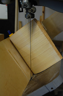
The most complicated part of the design is where the X-bracing on the sides hits the floor. When I fabricated this part before I made the lamination wider and then bandsawed the bent form at an angle to achieve what appeared to be a compound curve.
After thinking about the project a bit, I decided that this would be a poor detail and really mar the intent of the design. At the size of ply I am using (3" x 1/16") I realized there is a lot of flexibility in the wood and it would be possible for the strips of wood to bend in the way I wanted them to, I just had to analyze the wood's bending geometry in order to make a mold with the correct compound curvature.
The pictures show how I mocked up what the curve would need to be. I drew parallel lines every 1/2" along the wood and used a laser level to record the x,y,z coordinates where each line meet the edges of the wood. I then plotted all the points out in Rhino and after connecting them I was able to generate two 3d splines which represented the edges of the curving surface.
At first I thought that was it, but after recreating the parallel lines I marked on the wood by drawing straight lines from the 3d points on opposite edges, something didn't make sense. Towards the center of the bend the parallel lines started to become slightly shorter, and I realized it was because they were no longer straight.
After looking back at the physical mock up, it was obvious that the horizontal and vertical plane the wood was pressed against was causing it to bend in the shorter direction as well. I marked where along each line the wood began to curve so I could correct the digital model. Here is a video of the digital model as it is now.
The color scheme at the end of the video is part of Rhino's curvature analysis. The areas where the surface is not green signifies that the local curvature is too great, and the surface is no longer developable (able to be unrolled to a flat plane). I have to continue to tweak the curves that are creating the surface until everything is green, and then I will have a digital copy of the physical model which I can use to create my compound formwork.


